Identifying a defective RAM IC on laptops with soldered memory
Warning: some information in this article is uncertain and based onto third-party reverse engineering efforts. Official documentation from the memory controller manufacturer is required, however Intel does not make it public. This only shows the idea to narrow down the fault. Additionally, other factors such as a PCB or CPU fault could be the cause and not the RAM ICs themselves (e.g. common failure on MacBook Air 13" 2011 with board number 820-3023).
Introduction
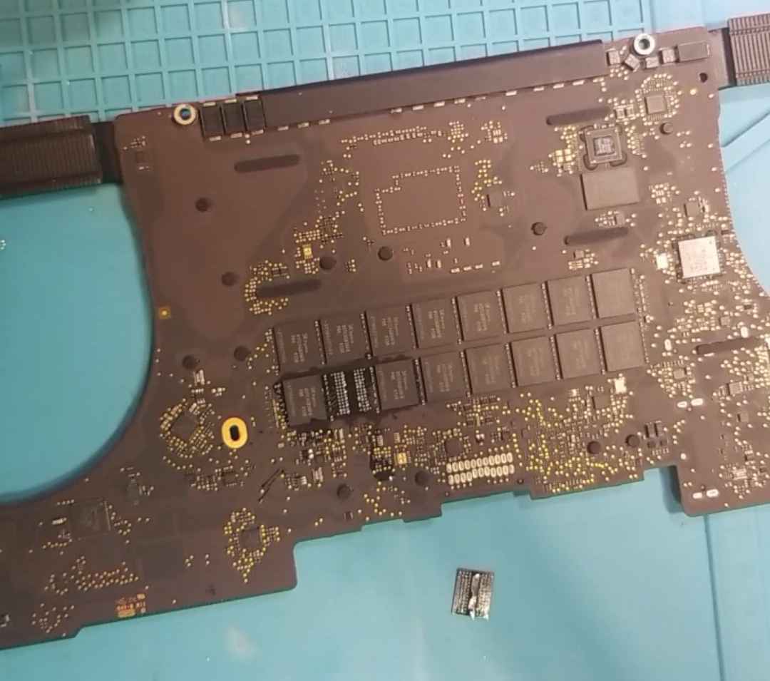
We will take the MacBook Pro Late 2013 15" IG with board number 820-3662 as a case study, in its 16 GiB RAM configuration which means fully populated with the 32 RAM ICs. This specific logic board was not passing ASD EFI memory tests.
Each RAM IC has a data bus with of 8 bits, so 8 ICs are needed for the full 64-bit width data bus found in modern PCs. On top of that, there are two memory channels and 2 ranks per channel for a total of 4×8=32 ICs. This also means that 1 data bit on the memory data bus has 4 associated ICs.
The memory controller does the mapping from physical addresses as seen by the CPU to the actual channel, rank, bank, row and column.
Note that under an operating system, the software executing on the CPU will see virtual addresses and not physical addresses, the operating system manages the virtual address space and the MMU (Memory Management Unit), part of the CPU, does the translation between the two, but this not directly relevant here.
In this article, we want to narrow down a memory failure detected by Memtest86 to a single IC. Memtest86 will show the "physical" addresses but not exactly which IC is affected. Note that recent versions of Memtest86 — the commercial one in its paid version — added support for identification of affected ICs on DIMMs for some platforms only. No DDR3 platform is supported.
This requires that the system is able to POST and start Memtest86, i.e. no power due to shorted RAM IC or no POST (no chime or 3 beeps) cannot use this technique.
Find errors with Memtest86
Note that Memtest86 and Memtest86+ are not the same software. Memtest86+ is open-source and Memtest86 is proprietary. In this case we will unfortunately be using Memtest86. You can try using Memtest86+ if you want.
First, download Memtest86. Version v10.1.009 was used in this test, note that v10.1 will hang on some Apple machines including this MacBook, so use a newer version. (v10.1.009 is a pre-release specifically built for this bugfix)
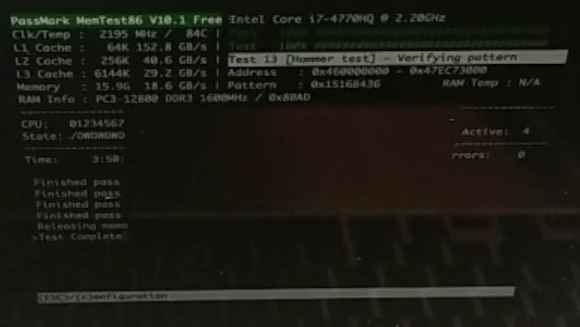
Let it run, this takes a few hours, and collect the results:
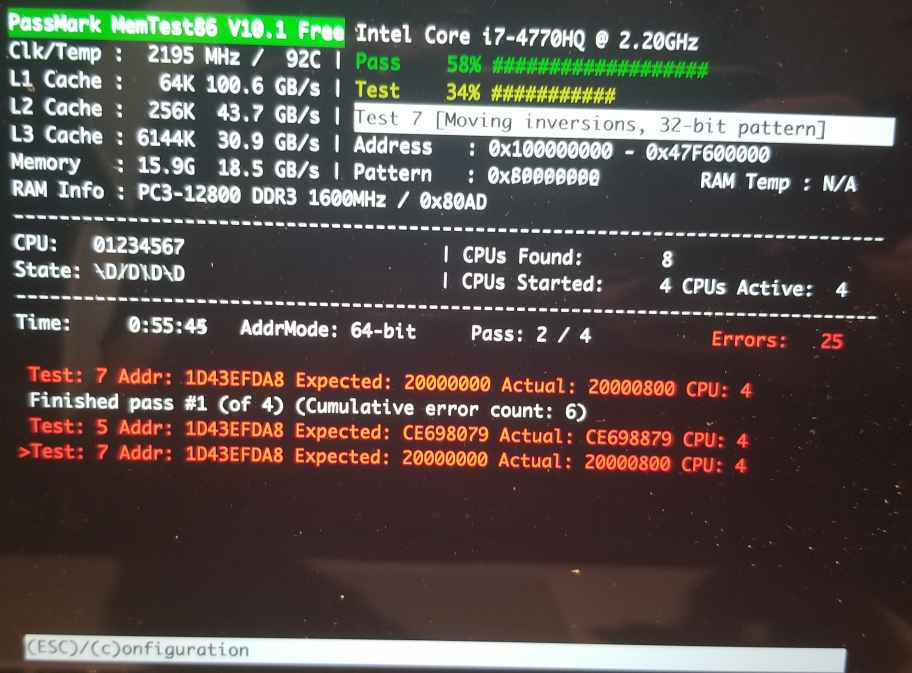
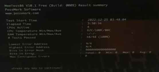
A summary page can also be displayed at the end.
In this case, failing bit is bit 11 (0x800 in binary is 0b100000000000), so it is one of the 4 ICs with data bus bit 11, i.e. U2310, U2410, U2510 or U2610. (This is explained in more details later.)
The failure is at memory address 0x1D43EFDA8.
Decoding address into channel and rank
Warning: this is the part with some uncertainties, proceed at your discretion.
Let's analyze 0x1D43EFDA8, in binary:
A = 0b1 1101 0100 0011 1110 1111 1101 1010 1000We will rely on a research article focusing on a memory attack, but providing reverse-engineered mapping for several platforms: https://www.usenix.org/system/files/conference/usenixsecurity16/sec16_paper_pessl.pdf
We can get the address mapping according to Table 2.a for Haswell in the 2 channels, 1 DIMM per channel configuration:
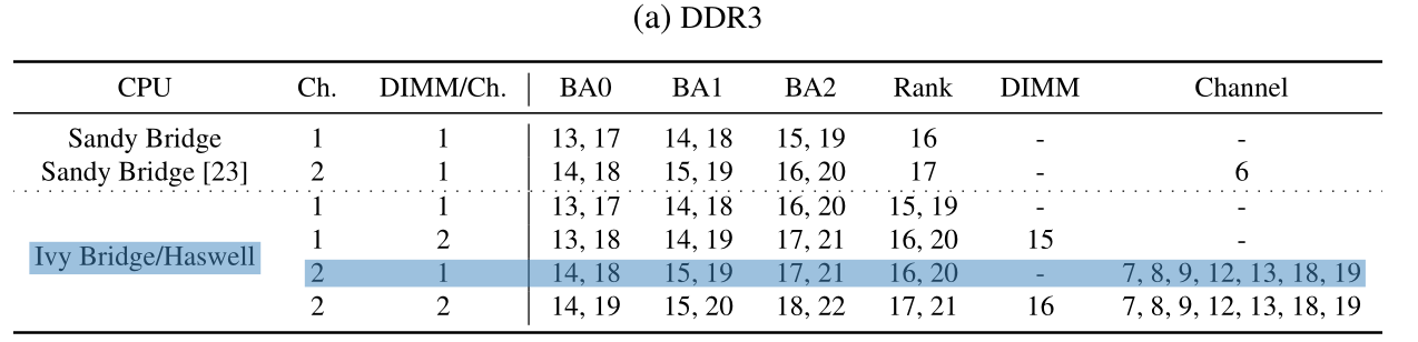
In the article linked above, all memory DIMMs used have 2 ranks. Having two DIMMs of 2 ranks on the same channel would mean a total of 4 ranks. Our board does not have discrete DIMMs as it uses soldered ICs, however it uses 2 ranks per channel (not 4). Therefore we assume a configuration of 1 DIMM per channel with 2 ranks.
In this table, each number is a bit position in the address, and an exclusive OR (XOR, noted ⊕ thereafter) is applied successively with each bit in increasing order. As a reminder, XOR outputs 1 only if both operands are different. It outputs 0 if both operands have the same value.
The bank address bits (BA0, BA1 and BA2) are used to address banks internal to all RAM ICs, so they are not relevant in our case.
So let's take a look at the rank first. It's a simple XOR between bits 16 and 20:
A[16] ⊕ A[20] = 0 ⊕ 1
              = 1
The address corresponds to rank 1, which means CS# signal bit 1.
The channel computation is more complex as there are 7 different bits involved:
  A[7] ⊕ A[8] ⊕ A[9] ⊕ A[12] ⊕ A[13] ⊕ A[18] ⊕ A[19]
=   1  ⊕   1  ⊕   0  ⊕   1   ⊕   1   ⊕   1   ⊕   1
=      0      ⊕   0  ⊕   1   ⊕   1   ⊕   1   ⊕   1
=             0      ⊕   1   ⊕   1   ⊕   1   ⊕   1
=                    1       ⊕   1   ⊕   1   ⊕   1
=                            0       ⊕   1   ⊕   1
=                                    1       ⊕   1
=                                            0
So the affect channel is channel 0, also called A.
Identify affected IC
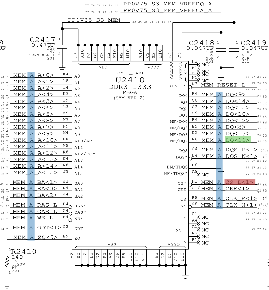
Then, we take a look at the schematics for the memory ICs:
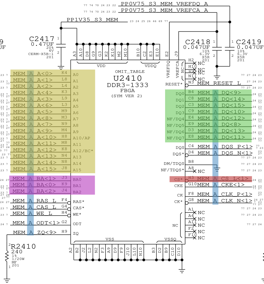
In this picture, the channel is highlighted in blue (MEM_*), the CS# signal for the rank is highlighted in red (MEM_*_CS_L<*>), the bank select bits are highlighted in purple (MEM_*_BA<*>), the row/column address bits are highlighted in yellow (MEM_*_A<*>), and finally the data bus is highlighted in green (MEM_*_DQ<*>).
We confirm that the memory IC is on channel A (MEM_A_*, in blue), is selected by CS# signal bit 1 (MEM_A_CS_L<1>, in red) and has data bit 11 (MEM_A_DQ<11>, in green):
We open the boardview with OpenBoardView to find where the IC is located:

Replaced affected RAM IC
We remove and then replace the IC. This require microsoldering equipment and skills. In this case the IC is taken from a donor board with an unrelated issue and reballed. RAM ICs are sensitive to heat so try not to overheat them.
Confirm the repair with Memtest86
Then we run Memtest86 again, which now passes successfully:
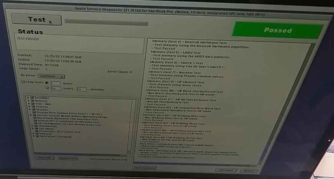
Same for Apple Service Diagnostic EFI 3S162: