Dell Factory Mode through SMSC MECxxxx JTAG
WARNING: the steps described below can and will brick your machine if performed improperly, make sure to always have a backup of your EC Flash and a way to recover from a bad flash. Additionally, this will void your warranty.
In this article, we will explain how to put a Dell motherboard back in factory mode, which allows changing the Service Tag among other things.
This tutorial is for motherboards using an SMSC MECxxxx Embedded Controller with embedded Flash. This has been tested with MEC5055 and MEC5075, it should work with other SMSC MECxxxx with embedded Flash but the JTAG ID and the page addresses may be different.
This requires decent soldering skills in order to interface with the unpopulated debug connector on the motherboard.
Requirements
Hardware
- A Dell computer using and SMSC MECxxxx with embedded Flash you want to put back in service mode.
- A JTAG probe compatible with OpenOCD. I will be using a Terasic USB Blaster but others such as FT2232-based ones should also work. Cheap USB Blaster clones are not recommended due to their unreliability.
- A 10 pins 0.5mm pitch FFC connector and cable. On some older boards, the footprint is 6 pins 1.2mm pitch.
- An FFC to DIP adapter board.
- Dupont cables to connect the adapter board to the JTAG probe connector.
- Alternatively: small jumper wires to solder on the motherboard debug connector.
- Microsoldering equipment.
Software
Another computer with:
- OpenOCD arc-2021.09, see below for installation.
- A hexadecimal editor (e.g., Bless on Linux).
- A network terminal such as Telnet.
- Schematics and ideally boardview files of the motherboard to locate the debug connector and its pinout.
- OpenBoardView to open the boardview file of the motherboard.
OpenOCD arc-2021.09
Either you can try to build OpenOCD arc-2021.09 yourself or you can download it pre-built as part of the GNU Toolchain for ARC Processors 2021.09. Choose one or the other option.
Build OpenOCD arc-2021.09
Modern compilers will not accept to build the original upstream release.
If you are building on an older OS (e.g., Ubuntu 20.04) it should be fine, but a system with GCC 13 will definitely not work.
I made a fork with the least backported patches required to build the arc-2021.09 release on newer systems: https://github.com/piernov/openocd
You will need the usual build tools and some development libraries as well, for example on Ubuntu:
sudo apt install build-essential libusb-dev libftdi-dev libhidapi-devThe steps to build it are the usual clone repository, generate autoconf files, configure, make and install:
git clone https://github.com/piernov/openocd.git -b arc-2021.09
cd openocd
autoreconf -fi
./configure
make
sudo make install
Note that this will install system-wide without tracking from the package manager, which is not recommended but easier.
Get GNU Toolchain for ARC Processors 2021.09
Got to https://github.com/foss-for-synopsys-dwc-arc-processors/toolchain/releases/tag/arc-2021.09-release and download the GNU Toolchain for ARC Processors IDE 2021.09. For example on Linux: https://github.com/foss-for-synopsys-dwc-arc-processors/toolchain/releases/download/arc-2021.09-release/arc_gnu_2021.09_ide_linux_install.tar.gz
Warning: the download exceeds 1 GiB and once extracted it will need 5 GiB more disk space.
Extract it somewhere, open a Terminal at this location and check if openocd can be executed:
./bin/openocd -vWhich should print:
Open On-Chip Debugger 0.9.0-dev (2021-12-09-11:36)
Licensed under GNU GPL v2
For bug reports, read
        http://openocd.sourceforge.net/doc/doxygen/bugs.html
Connect the JTAG probe
Now you need to connect the JTAG probe to the target system's debug connector.
Open the schematics of the motherboard and look for the SMSC MECxxxx.
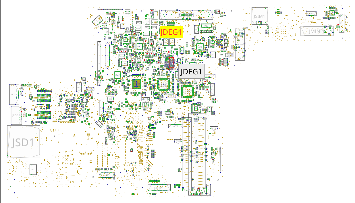
For example, in the block diagram of Compal LA-9832P we can see the MEC5075.
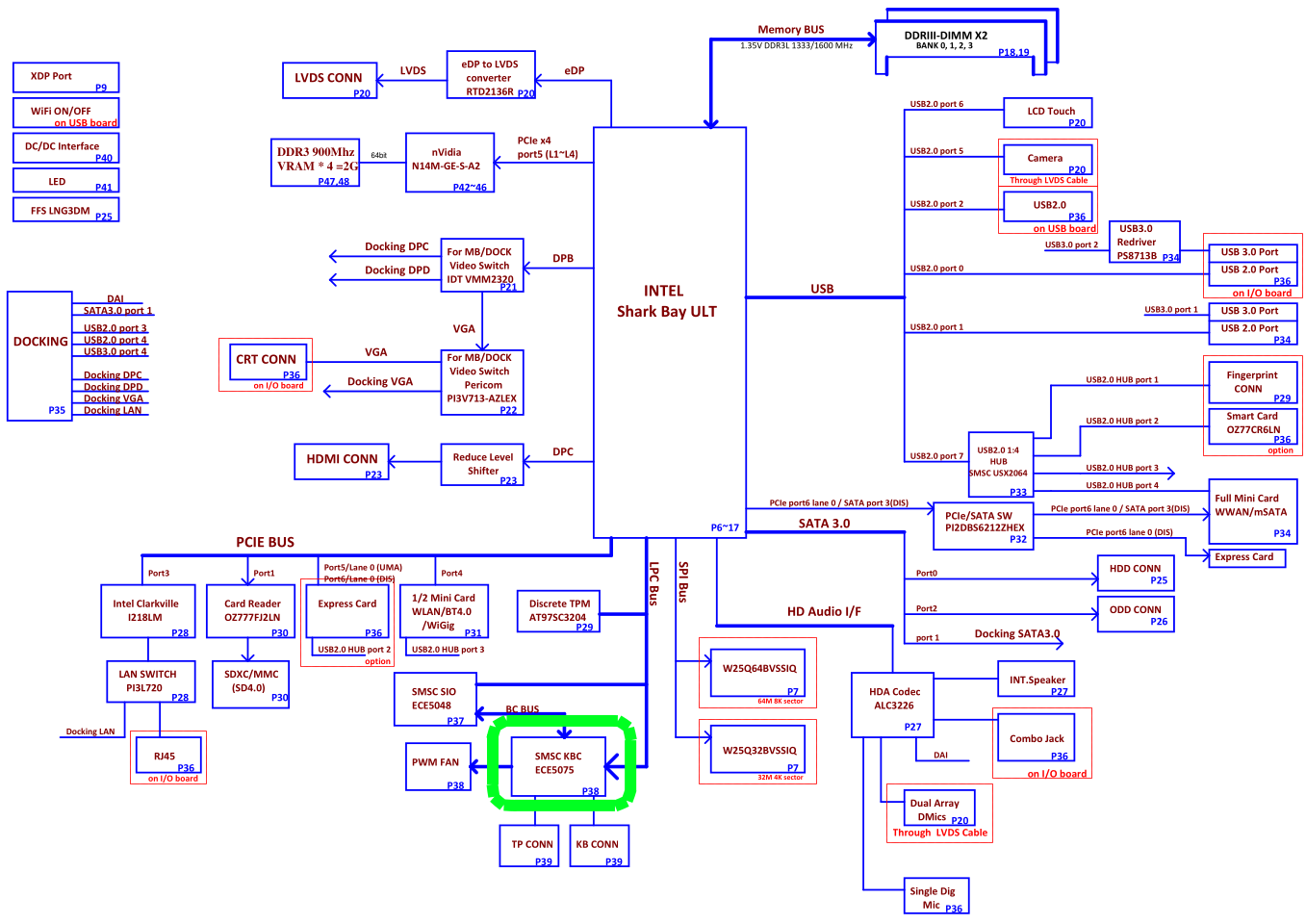
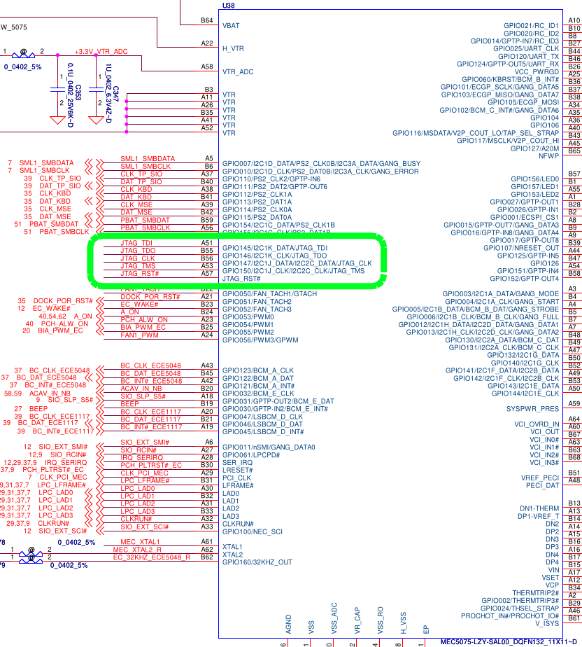
Its circuit is on page 32, with the reference designator being U38. We can easily see its JTAG interfaces with the TDI, TDO, TMS and TCK signals (as well as the optional TRST#).
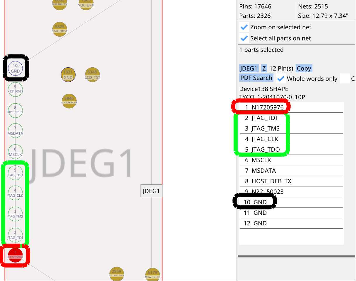
This interface is exposed on the JDEG1 connector. We will need to connect to the 4 JTAG signals (in green: TDI, TMS, CLK, TDO), as well as power (in red: +3.3V_ALW) and ground (in black).
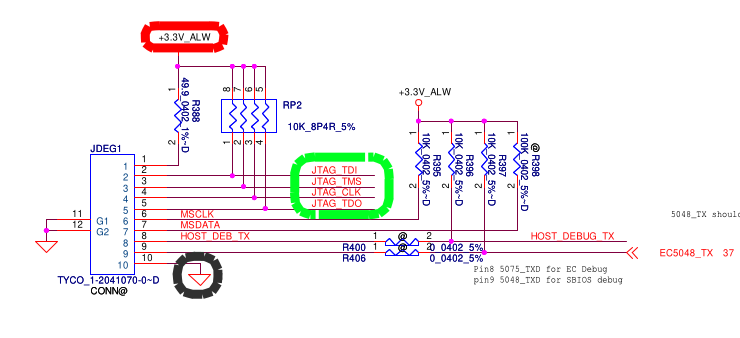
The power rail is used for the JTAG probe to set its levels correctly. Some JTAG probes may instead be permanently set to 3.3V (confirm with its manual, do not use a JTAG probe fixed to another voltage level). The JTAG Probe does not supply power to the board, we will need to keep the AC adapter connected.
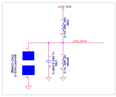
The JTAG_RST# signal is not available on this connector but we do not need it. However, if the JTAG_RST# signal is pulled down, the JTAG interface is disabled, so it may stay pulled up. On this board, it is pulled up by default since R384 is not populated (annotated with @) and the JTAG1 pads are not shorted:
With help of the boardview, we can easily locate the debug connector on the keyboard side:
With our 4 JTAG signals, power and ground:
If you have a connector, cable and adapter board that fit, solder the connector onto the board. You do not need to solder the anchor pads if you want to remove the connector more easily after the operation, just make sure to not put force on it to avoid ripping off the pads.
Using a connector makes the job much easier. See this example:
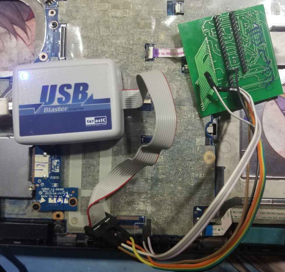
Otherwise, you need to solder jumper wires to these 6 pads.
Then, connect to your JTAG probe. Read the manual of your probe to figure out its pinout. For example, for a USB Blaster:
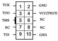
This would be the board connector top view. Therefore, if you look at the connector at the end of the USB Blaster cable, the pinout is mirrored.
Generally, you need to swap the connection between TDI and TDO compared to the pinout of the board. If you cannot establish communication, just try to reverse these pins, it is harmless.
Establish connection with OpenOCD
Now that the USB Blaster is connected to the target board, connect the JTAG Probe to the host computer.
Create a new openocd.cfg file with the following content:
source [find cpu/arc/arcompact.tcl]
source [find cpu/arc/em.tcl]

set _CHIPNAME arc600
set _TARGETNAME $_CHIPNAME.cpu

jtag newtap $_CHIPNAME cpu -irlen 4 -ircapture 0x1 -expected-id 0x200024b1

target create $_TARGETNAME arc600 -chain-position $_TARGETNAME

arc jtag wait-until-write-finished on
$_TARGETNAME configure -event reset-assert "arc_arcompact_reset $_TARGETNAME"

arc_arcompact_init_regs
The -expected-id 0x2000024b1 works for MEC5075, it needs to be changed to -expected-id 0x1000024b1 for MEC5055.
Plug the AC adapter to the target system and run OpenOCD:
openocd -f interface/altera-usb-blaster.cfg -f openocd.cfgIf you are running from the GNU Toolchain for ARC Processors, you will instead have to run OpenOCD like this:
./bin/openocd -s ./share/openocd/scripts -f interface/altera-usb-blaster.cfg -f openocd.cfgYou will need to change the interface/altera-usb-blaster.cfg configuration file according to your JTAG probe if you are not using a USB Blaster.
This should print something similar to:
Open On-Chip Debugger 0.9.0-dev-dirty (2023-07-22-18:20)
Licensed under GNU GPL v2
For bug reports, read
	http://openocd.sourceforge.net/doc/doxygen/bugs.html
Warn : Adapter driver 'usb_blaster' did not declare which transports it allows; assuming legacy JTAG-only
Info : only one transport option; autoselect 'jtag'
Info : No lowlevel driver configured, will try them all
Info : usb blaster interface using libftdi
Info : This adapter doesn't support configurable speed
Info : JTAG tap: arc600.cpu tap/device found: 0x200024b1 (mfg: 0x258, part: 0x0002, ver: 0x2)
Info : accepting 'telnet' connection on tcp/4444
If you have an error such as JTAG scan chain interrogation failed: all ones, it generally means the JTAG probe is not hooked up properly to the target system.
An error similar to unable to open ftdi device: usb_open() failed is generally a permission error on the host system, try prepending sudo to the command.
You can now open another terminal to connect to the OpenOCD server with Telnet:
telnet localhost 4444You should be welcomed with OpenOCD prompt. This is where you will be typing commands to interact with the SMSC MECxxxx.
Dump current firmware
In the OpenOCD terminal, type:
halt
dump_image mec_backup.bin 0x0 0x48000
This will dump 288 KiB (0x48000) of memory starting at address 0 (0x0) from the MECxxxx. Since the Flash is mapped at address 0, this has the effect of dumping the Flash content (except protected pages, see below).
MEC5075 has 288 KiB of internal Flash, other models may have a different amount of Flash so this value may need to be adjusted.
OpenOCD should print something similar to:
dumped 294912 bytes in 294.752319s (0.977 KiB/s)Depending on the JTAG probe and its configuration, this can take several minutes. Be patient, do not touch the target system.
Unlock boot block (optional)
Some pages are generally protected, generally the first 4 KiB are not readable and will appear blank (0xFF). This should not be an issue here as we do not need to interact with these pages.
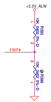
If you want to read these as well, you can pull the NFWP pin or FWP# low instead of high. For example, on Compal LA-9832P, you can move R393 to R399.
Analyze firmware
In this step, we will look at the dumped firmware to identify which pages should be erased to put the board back in manufacturing mode (erasing seralization). Open the firmware in a hexadecimal editor (Bless on Linux for example) and search for the current service tag in text mode.
There should be two occurences, separated by 0x800 which is incidentally the size of a page. Find the beginning of both pages, i.e. addresses multiple of 0x800 just before where the service tag was found.
This can vary between machines and maybe firmware versions, on Compal LA-9832P the pages address have been observed to be 0x47000 and 0x47800, and on Inventec Krug 14" UMA they were 0x3f000 and 0x3f800.
Erase pages
Once we identified the addresses to erase, we can actually erase them.
Warning: if you did not properly identify the pages to erase or if you enter the commands improperly, this will brick your machine. Do not proceed if you are not confident in what you are doing and if you cannot risk bricking the motherboard!
Erasing these 2 pages should not cause any problem except for the fact that you will need to enter the service tag again, erasing any other page will probably cause the motherboard not to turn on anymore!
It is also important to note that while we did make a backup of the firmware previously, there is currently no easy way to restore it with this toolset. You will need to use a dedicated EC programmer. This is because there is currently no Flash driver or script to make it easier to program multiple addresses at once in an SMSC MECxxxx using OpenOCD.
Now that this is said, you can proceed with caution and enter the following commands in the OpenOCD terminal:
## Erase first page
reset halt
mww 16726288 1
mww 16726280 256
mww 16726284 1792

mww 16726280 259
mww 16726276 <first page address>
mdw 16726284


## Erase second page
reset halt
mww 16726288 1
mww 16726280 256
mww 16726284 1792

mww 16726280 259
mww 16726276 <second page address>
mdw 16726284
Replace the page addresses by the one you found in the previous section.
In this script, we first initialize the Flash controller, then tell it to enter erase mode, and send it the address of the page to erase, then display the content of the status register. You can read the EMBEDDED FLASH SUBSYSTEM section of the MEC1618 datasheet for more information.
Wait for a few seconds between erasing the first page and erasing the second page since the Flash controller will still be busy as indicated by the status register: each mdw 16726284 commands will show 0x00ff390c: 00000029, in binary the right-most bit is 1 which means busy.
However, do complete the entire set of commands rather quickly: the SMSC MECxxx will reset by itself after a short while, there is probably a watchdog in place.
Enter new service tag
At the next reboot of the machine, you will be greeted by a warning saying that the machine is in manufacturing mode and is missing its service tag.
If you do not need manufacturing mode, you can exit it by pressing Alt+F during boot.
In any case, you will need to enter the service tag in the UEFI setup, otherwise the warning prompt will show up at each boot.
References
- https://gist.github.com/four0four/680e1fa70e7c216baac2afbd459d03d8
- https://github.com/GlasgowEmbedded/glasgow/blob/main/software/glasgow/applet/program/mec16xx/__init__.py
- https://svod-project.com/svod3/MEC5075 on Latitude E7440 (LA-9591P).pdf
- https://ww1.microchip.com/downloads/aemDocuments/documents/OTH/ProductDocuments/DataSheets/00002339A.pdf